Wall Footings - Design
Here we will talk specifically about the calculations for wall footings.
- For more information on defining wall parameters, see Wall Footing Definitions.
- For more information on modeling requirements, see Wall Footings - Modeling.
- For more information on the output, see Wall Footing Results
RISAFoundation currently designs wall footings for all of the ACI codes, as well as the CSA A23.3-04/14 Canadian code. In this topic we will make specific reference to provisions for some of these codes. Note that the only differences in behavior with the differing codes is with the reinforcement design. All soil and serviceability checks are identical across codes.
Soil Considerations
The following details discuss some of the considerations for the computation of soil pressures.
Lateral Force Coefficient (K) Calculations
From the Wall Footing Definition Editor (or the Wall Footing Definitions Spreadsheet), you can define either Rankine or Coulomb for the Lateral Earth Pressure Methodology.
Rankine
You can define the coefficient of internal friction (φ) and backfill angle (θ) in the Wall Footing Definition Editor (or the Wall Footing Definitions Spreadsheet) and allow the program to calculate K. Alternatively, you can directly input the K factors. If the program is used to calculate K, these are the equations used:
- The calculation of Ko assumes normally consolidated granular soil.
- Ka and Kp are calculated considering Rankine theory.
- Because of the use of Rankine theory, battered retaining walls behave identically to walls with uniform thickness for hydrostatic loading.
Coulomb
You can also directly input K with the Coulomb method and the program will ignore the other values. If the program is used to calculate K, these are the equations used.
where:
- θ = Backfill angle
- φ = Soil friction angle
- δ = Wall friction angle
-
α = Wall slope angle measured from horizontal (90 degrees for a vertical wall face)
Both Methods
There is a potential to have three K factors for a single retaining wall: K Heel, K Sat Heel and K Toe.
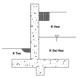
Figure 1: Three Possible K factors
- If the wall is a cantilever, the program will use the Ka equation for the heel side K factors and Kp equation for the toe side K factors.
- If the wall is a propped cantilever, the program will use the Ko equation for both the heel and toe K factors.
- RISAFoundation performs a calculation to compare the total passive forces to the active forces. If the passive forces exceed the active force, the wall is assumed to be in an at rest condition and the program will use the Ko equation for both the heel and toe K factors. When this occurs, the wall footing detail report will show (At Rest) after both the heel and toe K factors.
Lateral Soil Summation
The program will perform a calculation comparing the total active force from the heel side and the total passive force from the toe side. If the passive force exceeds the active force, you then have an irrational solution. In this case, the program will give a message in the Detail Report and not design your retaining wall. The message states "The hydrostatic passive forces (toe side) exceed the hydrostatic active forces (heel side). Consider manually entering K factors for this wall." In this case, the Rankine active vs passive pressures will not work, so instead you may need to manually input your K factors in the Wall Footing Definitions Spreadsheet.
Loading Considerations
Regarding the loading of retaining walls, all hydrostatic, soil and surcharge loads are taken into account on a per foot basis. For more information, see Wall Footings - Modeling. Externally applied loads to retaining walls or strip footings are summed over the entire length of the wall and then divided out on a per foot basis. Because of this, concentrated stresses and areas of the wall that require tighter reinforcement are not taken into account. For more information on applying external loads to the model, see Wall Footings - Modeling.
Seismic Loading Considerations
RISAFoundation will consider an inverted triangular seismic loading diagram if:
- The "EL" category specifically is used in the load combination.
- The Coulomb method is used for the Lateral Earth Pressure Methodology
There are two paths to applying your seismic loads:
User Define the Magnitude of the Maximum Value of the Diagram
In the Wall Footing Definitions - Soil tab, there is an input for EQ Max. If there is a value in here, this is used as the maximum.
Allowing the Program to Calculate this Magnitude Using the Mononobe-Okabe/Seed-Whitman Formulation
In the Wall Footing Definitions - Soil tab, there is an input for EQ Max and Kh. For the program to calculate the magnitude of the maximum value of the diagram, EQ Max should be left blank and a value for Kh should be input.
The Mononobe-Okabe/Seed-Whitman equation is an expression for the total lateral earth force, including seismic plus active forces. Thus, to calculate the portion due solely to seismic, we must remove the active pressure portion. The M-O pressure coefficient is calculated as follows:
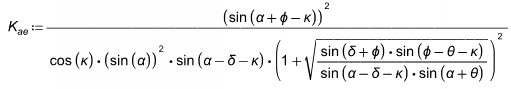
where:
- θ = Backfill angle
- φ =Soil friction angle
- δ = Wall friction angle
- κ = Seismic Factor = tan-1(Kh)
- Kh = Input on Soils tab
-
α = Wall slope angle measured from horizontal (90 degrees for a vertical wall face)
The new term here is κ. This value uses the input Kh value for the Design Horizontal Ground Acceleration (in g). Kh is generally defined as Sds/2.5, but the actual value is up to the user. The vertical component of earthquake acceleration is not considered in the program.
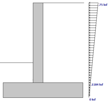
The total seismic lateral force (per foot) is then defined as:
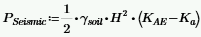
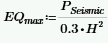
Per the Seed-Whitman variation, this seismic force is assumed to act at 0.6*Hwall. Thus, to calculate the magnitude at the top of the wall this equation is used:
- Seismic calculations only apply to the Coulomb Lateral Earth Pressure Methodology.
- Seismic is ignored if K factors are hard-coded and EQ Max is left blank in the Wall Footing Definitions - Soil tab.
- Seismic is ignored if the wall is propped at the top.
Serviceability Considerations
Overturning and sliding checks are only provided for Service load combinations (LC's with the Service check box checked).
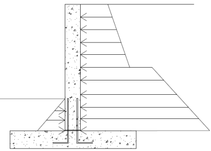
Overturning
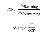
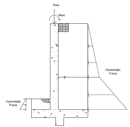
Overturning is checked at the base of the footing at the extreme edge of the toe. Each portion of soil weight, concrete weight, surcharge loading, lateral soil pressure and lateral water pressure is taken into account. Each piece is either part of the resisting moment or the overturning moment.
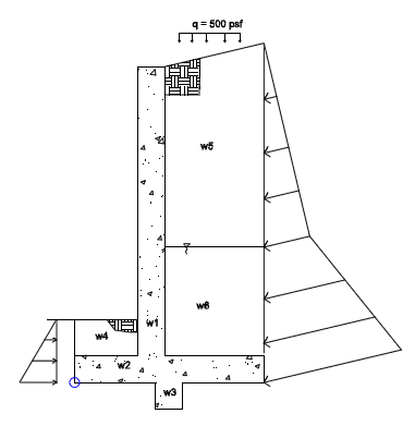
Figure 2: Overturning Diagram
From here, all of the resisting moments and overturning moments are summed. The ratio of resisting moments to overturning moments is checked against the SF given in that individual load combination.
- If the wall is a strip footing there is no consideration for lateral hydrostatic forces. Only vertical soil loads, self-weight and external forces are considered.
- If the wall is a propped cantilever the overturning checks will be omitted.
- The program considers the passive soil resistance from the toe in overturning considerations.
- For sloped backfills, the vertical component of the hydrostatic load will be included in the resisting moment.
- The presence of a key has no bearing on overturning except that the weight of the key will be accounted for.
Sliding
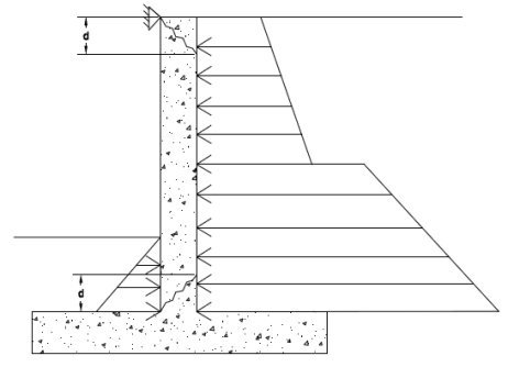
Sliding is checked at the extreme bottom face of the footing. This occurs at the bottom of footing if there is no shear key. If there is a shear key, this occurs at the bottom of the key.
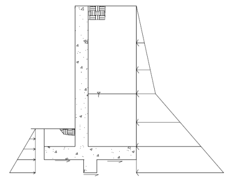
Figure 3: Sliding Forces Diagram
Both the passive soil pressure and friction resistance are accounted for.
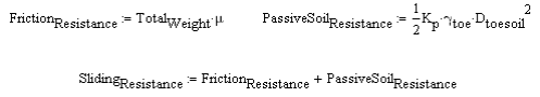
where:
- Total Weight = Total downward force acting on the footing due to soil, concrete and surcharge forces.
-
μ = Soil coefficient of friction defined in the Model Settings - Solution tab.
The sliding resistance is then compared against the sliding force caused by the hydrostatic pressure. The ratio of resisting forces to sliding forces is checked against the SF given in that individual load combination.
![]()
- Deflection calculations for the top of the wall are not given.
- Sliding is not checked for retaining walls where the footing is restrained or if the top of the wall is propped.
- For strip footings, the hydrostatic lateral forces from either the heel or the toe are not considered. Sliding is only resisted by frictional forces.
Stem Wall Design Considerations
Stem walls can be made of concrete or masonry materials. Design details for walls made with each of these materials are discussed below.
General Considerations
The stem wall design is analyzed along its height to come up with axial, shear and moment diagrams. The wall is designed for the worst case forces at the critical section. The program checks 20 locations over the height of the wall to determine the critical section. For a cantilevered uniform stem wall, the critical section is always at the wall intersections with the top of footing. For a propped retaining wall and/or one with a batter, this will be somewhere along the length of the wall. The program will take any externally applied loads in combination with hydrostatic pressures, surcharges, etc. The program will then factor the loads according to load combinations to come up with the axial, shear and moment diagrams.
- Because the combined effects of the flexural deflection of the stem and the rotational deflection of the overall wall/footing is generally small and hard to quantify, wall deflections are not considered in the analysis, .
- Strip footing stem walls require the soil height to be equal on both sides. Thus, hydrostatic forces are ignored. Only applied forces will induce any bending into a strip footing stem wall.
- The vertical portion of that load will be assumed to act at the top of the wall and be included in the axial force in the wall if there is a sloping backfill.
- P-Delta (big and little) is not considered for stem walls. Typically, axial forces are small in retaining walls and P-Delta will have little effect.
Concrete Wall Considerations
For concrete walls, the stem wall design is only considered for non-service load combinations.
Axial/Bending Design
The program, given the wall thickness, reinforcement sizes, and max and min spacing and spacing increment, will design the wall reinforcement spacing to meet strength and minimum steel requirements.
The program will start with the maximum spacing. If that does not work for design, the spacing will drop by the spacing increment and be checked again. The program will work its way down until it reaches a spacing that meets all reinforcement requirements. The wall is checked considering the entire wall as a column. Thus, interaction and compression reinforcement is considered in the code check. Results are presented on a per foot basis, so the entire wall demand and capacity is calculated and then divided out on a per foot basis.
- The exact location and number of bars in the wall is used in capacity calculations. Use the As Provided in the Detail Report when doing any hand calculation verification.
- Reinforcement checks include the minimum reinforcement requirements of ACI 318-14 Section 11.7, ACI 318 Section 14.3 and CSA A23.3-04 Clause 14.
- For battered retaining walls, the controlling section will be reported, though this may not be the location of maximum moment.
- For battered retaining walls, the reinforcement on the battered face of the wall will be parallel to the face.
Moment and Axial Force Thresholds
The program will ignore axial forces and moments that are below a certain threshold. If the moment or axial force is deemed to be inconsequential to the code check, the program will not include the interaction of that force. There are two thresholds that are considered:
- Axial Force Threshold: If Pu < 0.01*f'c*Ag for a LC, the axial force in the wall will be ignored for code checks for that LC.
- Moment Threshold: If Mu < 0.01*d*Pu for a LC, the moment in the wall will be ignored for code checks for that LC.
These two thresholds allow the concrete solver to work much more efficiently while having little to no effect on code check values.
Shear Check (Concrete)
The program will perform a concrete shear check. This check is taken at a distance "d" from the top of footing for a cantilevered wall. It is taken at a distance "d" from both the top of footing and from the top of the wall for a propped cantilevered wall.
- This check will occur at 20 sections along the height of the wall and the worst case code check will be given in the results for a battered retaining wall.
- The shear check does not consider axial force. The program check is using the ACI 318 equation (and a similar equation for the CSA A23.3-04):
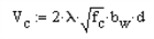
Masonry Wall Considerations
For masonry walls, per the Model Settings, you can use either ASD or Strength code checks. Stem wall design is only considered for non-service load combinations. Here, we will break down both ASD and Strength aspects. Codes currently supported for masonry include:
- The 2022 and 2016 TMS 402 ASD and Strength codes.
- The 2013 ACI 530 ASD and Strength codes.
ASD Design Considerations
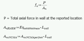
Axial Stress, fa
The axial stress in a wall due to axial forces, fa, is calculated as:
Axial Capacity, Fa
The calculation of Pa for reinforced masonry is Equation 8-16 or 8-17 and Fa for unreinforced masonry is per either Equation 8-11 or 8-12. depending on the h/r ratio. The equations are as follows:
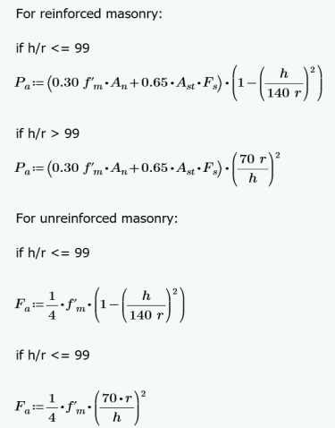
where:
- r is taken from the UBC-97 Table 21-H-1 (concrete masonry units) and Table 21-H-2 (clay masonry units).
- h = Total height of wall
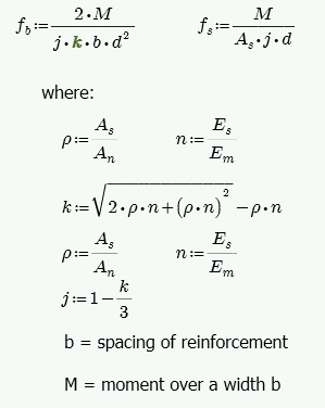
Stresses fb and fs
The masonry bending stresses are referenced in UBC Section 2107.2.15 and are as follows:
However, if you are using a partially grouted wall where the neutral axis passes through the webs of your masonry, RISA will do a T-section analysis to define the section properties. We use a similar analysis as if you were doing a t-beam analysis for a concrete tee section. For more information on this, see "Design of Reinforced Masonry Structures" by Narendra Taly, copyright 2001, example 6.3, P6.61.
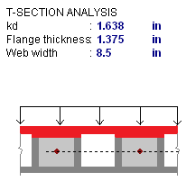
The area in red represents the compression block in the image above.
Bending Capacity, Fb
For unreinforced masonry, Equation 8-13 is:

For reinforced masonry, Section 8.3.4.2.2 states:
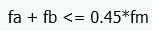
Because of this provision, RISA defines:
Steel Capacity, Fs
Section 8.3.3.1 defines the allowable steel stress, Fs.
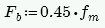
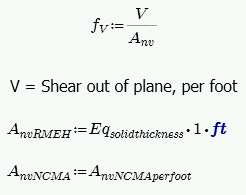
Shear Stress, fv
This stress is calculated from Equation 8-19:
Shear Capacity, Fv
The program calculates the capacity, Fv, from Equation 8-20, except that only the Fvm term is considered. There is no way to add shear reinforcing steel. The program also checks to verify we do not exceed the Fv max value from Equations 8-21 and 8-22 (or interpolation between them) that is reported in the detail report.
Strength Design Considerations
Axial Strength, Pn at max Mom
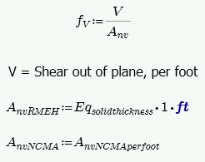
Here there are two different possible calculations. If there is out-of-plane moment on the walls (from a retaining wall, for example), this is calculated from Section 9.3.4.4.2 as follows:
-
If h/t < 30, Pn at max Mom = 0.20*f'm*An
- If h/t > 30, Pn at max Mom = 0.05*f'm*An
If there is no out-of-plane moment (from a strip footing, for example), this is calculated from Equations 9-11 and 9-12:
- t from the above equations is taken as the Block Nominal Thickness.
- h = Height of wall region.
Moment Strength, Mn
This calculation comes from the Commentary of Section 9.3.4.2 as follows:
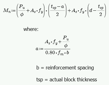
The program is actually using an interaction diagram for out of plane bending as well. However, the code places a limit on axial force from Section 9.3.4.4.2. This limit essentially means that only the lower portion of the interaction diagram will be used. In this lower portion of the interaction diagram, the bending capacity changes in a linear fashion with respect to axial force.
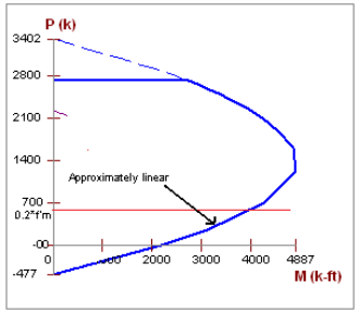
Thus, the equation above is nearly identical to the value that the program's interaction diagram will produce.
- In the case of high axial tension, it is possible that moment capacity will near zero.
- In partially grouted walls, an effective width is calculated for b from Section 5.1.2.
ASD Masonry Design For Unreinforced Walls
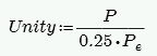
Compression Check (per Equation 8-9)
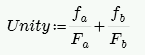
where:
- fa and Fa are computed the same way as for reinforced masonry.
- fb = M/S. S = Sx value from NCMA TEK 141B (regardless of Wall Area Method designation).
- Fb = 1/3*f'm per Equation 8-15
Tension Check (per Section 8.2.4.2)
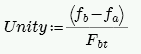
where:
- Fbt = Allowable flexural tensile stress per Table 8.2.4.2
Slenderness Check (per Equation 8-10)
where:
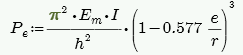
- Per Equation 8-14.
- I comes directly from NCMA TEK 141B for both Wall Area Methods, NCMA and RMEH.
- e is always assumed equal to 0.
- h = Height of wall
Shear Design (per Equation 8-19)
The program calculates the capacity, Fv, from Equation 8-20 shown above. The program also checks to verify we do not exceed the Fv max value from Equations 8-21 and 8-22 (or interpolation between them) that is reported in the Detail Report.
Footing Design Considerations
Here we will discuss some of the details of footing and dowel design (shear friction). Note that footing design is only considered for non-service load combinations. Shear friction checks are strength level checks.
Shear Friction Check (for dowels between the wall and footing)
If the stem wall is not poured monolithically with the footing, a shear friction check is required at the base of the wall. This check considers the dowels from the footing to the wall and the program assumes that these dowels match the vertical reinforcement (either on the inside face or both faces; see Wall Footing Definitions for more information).
ACI 318 Codes
This check is done using ACI 318-14 Equation 22.9.4.2 (ACI 318-11 Equation 11-25) for shear friction:
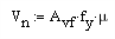
where:
- Avf = the reinforcement that crosses the shear plane
- μ = 1.0*λ for intentionally roughened surface; 0.6*λ for a smooth surface
CSA A23.3-04 Code
This check is done using the CSA A23.3-04 shear friction capacity equation (11-24):
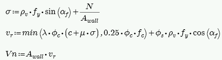
where:
- N = unfactored dead load acting on the wall (1.0*DL)
- αf = angle between shear plane and reinforcement (always taken as 90 degrees)
- ρv = ratio of shear friction r/f to total wall area (from Eq 11-27)
- λ = factor for lightweight concrete
- c and μ = taken from Clause 11.5.2
- Avf = the reinforcement that crosses the shear plane
ACI 530-13 Masonry Codes (ASD & Strength)
This code uses the ACI 318 procedure discussed above.
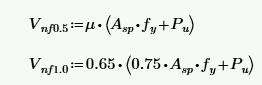
TMS 402-16 and 402-22 Masonry ASD
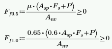
This check is done using Equations 8-28 and 8-29 for TMS 402-16, depending on the M/Vd ratio:
The check uses Equations 8-25 and 8-26 for TMS 402-22, depending on the M/Vd ratio:
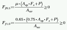
where:
-
μ = coefficient of friction, 1.0 rough, 0.7 smooth
- Asp = area of reinforcement within net shear area
- Anv = net shear area
- Fs = Allow reinforcement stress in tension/compression
- P = axial load
TMS 402-16 and 402-22 Masonry Strength
This check is done using Equations 9-33 and 9-34 for TMS 402-16, depending on the M/Vd ratio:
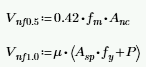
This check is done using Equations 9-33 and 9-34 for TMS 402-22, depending on the M/Vd ratio:
where:
-
μ = coefficient of friction, 1.0 rough, 0.7 smooth
- Asp = area of reinforcement within net shear area
- fy = yield stress in steel
- Anc = net cross-sectional area between neutral axis of bending and fiber of max compressive strain, = beff*c.
- Fs = Allow reinforcement stress in tension/compression
- P = axial load
- The coefficient in the μ factor is defined by the Wall/Foot Continuity? entry in the Wall Footing Definitions Spreadsheet.
- The shear friction check is omitted for strip footings, as loads are generally vertical as opposed to lateral.
Soil Pressure Considerations
Calculating the pressure under a footing requires both the moment (M) and the axial force (P) on the centerline of the footing at the base. An alternative hand calculation approach is to take the sum of moments (factored) from the overturning check and divide that out by the total axial force (factored). This gives you the resultant force location from the toe end.

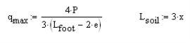
From the x-value you can calculate the eccentricity from the footing centerline as:

If the resultant is in the middle third of the footing the force distribution is:
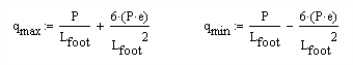
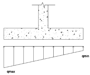
If the resultant is outside the middle of the footing, the force distribution is:
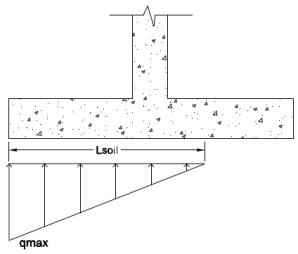
The soil (and surcharge) bearing down on the soil is also considered:
- Many design examples may disregard certain portions of load for conservatism or for ease of calculation, however, the program uses the exact loading conditions defined.
- Per ACI 318-14 Section 13.3.1.2 (ACI 318-11 Section 15.7) the depth of footing above bottom reinforcement shall not be less than 6".
Flexural Design
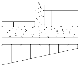
Flexural design for wall footings assumes that the heel and toe portions of the footing are designed as cantilevered beams from the face of the retaining wall. There are generally two deflected shapes that will occur for footings depending on the loading.
The left image is likely the most common for retaining walls. The right image will generally occur for strip footings. In either case, the program considers the moment at the face of both the heel and toe and designs reinforcement for the worst case load combination. Both the flexural reinforcement (parallel to the footing) and the shrinkage and temperature reinforcement (perpendicular to the footing) are designed for minimum steel requirements as well.
Shear Checks
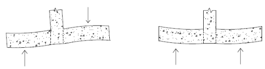
Shear design of footings also considers both the toe and heel sections as cantilevered beams. The difference here is where the shear failure will occur. The left image below shows the standard shear failure planes for typically loaded retaining walls. The right image below shows the standard shear failure planes for typically loaded strip footings. The program will check the loading of the footing and check the shear at the appropriate location.
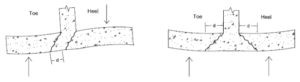
From the left image, you see that the shear check would occur at a distance "d" from the face of the toe and right at the face of the heel. From the right image, you can see that both the heel and the toe would have their shear check occur at a distance "d" from the face of wall.